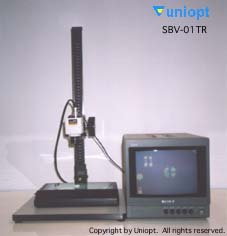
- Overview of SBV-01
The SBV-01 is a simple birefringence observer that can easily observe the magnitude of birefringence of a sample by replacing it with a color change. It is useful for relative comparison of birefringence and observation of birefringence distribution inside a sample. It is very effective for sorting work in the inspection process. The image taken by the CCD camera can be captured by a personal computer and registered in the image database (optional). By registering the standard samples in advance, it is easy to compare and sort the samples. By using a sample of known birefringence as a standard sample, a rough quantitative evaluation is possible. - Features
- Simple : Intuitive discrimination is possible because the magnitude of birefringence corresponds to the color change.
- High sensitivity: Humans are very sensitive to color. It is said that skilled operators can distinguish birefringence of 1 nm or less.
- Digitization: By registering the image to the image database, various applications become possible.
- Space saving: The basic configuration can be placed on an office desk for easy operation.
No pre-processing such as polishing is required. - Low cost
- Observation method
When there is no sample, the screen appears reddish-purple in color. This is the color when there is no birefringence. When a birefringent sample is inserted in front of the camera, the color changes to blue or orange depending on the magnitude of the birefringence. If there is a distribution of birefringence in the sample, the colored area will be observed as spots. Pay attention to the direction of the polarization axis indicated on the instrument beforehand. Birefringence changes cannot be observed in the direction of the polarization axis. In the picture below, the polarization axes are set to vertical and horizontal. In the picture below, the polarization axes are set vertically and horizontally, so you can see that there is no color change in these directions. In this case, to quantitatively compare the color change and the magnitude of birefringence, we need to look at the change in the 45 degree direction. Across the polarization axis, the birefringence changes color in two directions: orange and blue. This depends on the direction of the main axis of birefringence of the phasor used in the instrument. By using this color change, for example, it is possible to determine the birefringent phase axis in a sample (in the case of birefringence due to the photoelastic effect, it is possible to determine the compressive and tensile stress). - Applications
- Optical disk substrates
- Liquid crystal devices
- Polymer materials (plastic, vinyl, etc.)
- Optical glass
- Observation of photoelasticity
- All other optically transparent objects
- Observation method
- CD-ROM
 You can see that there is a birefringence distribution inside the circle and in the area indicated by the arrow. The photo on the right is an enlargement of the circle.
 This picture shows the pattern observed when the disk is tilted in various directions. It can be seen that the color of the observed birefringence changes depending on the direction of tilt. This helps us to understand birefringence in three dimensions in a rough and intuitive way.
- Floppy disk
 This photograph shows a part of the plastic case of a floppy disk. We can see that the birefringence is large in the notch area. From such observations, it is possible to quickly determine the molding conditions for polymer products. At the same time, by photographing the transparent scale, it is easy to check the actual size later. As can be seen in this example, as the amount of birefringence increases, the color changes in various ways and with a certain degree of periodicity.
- Electrode section of a TN liquid crystal panel
 This photograph shows an observation of the electrode of a TN liquid crystal cell. A change in birefringence is observed at the electrode and the lead wire. This may be due to a change in the thickness of the liquid crystal layer by the thickness of the electrodes, or it may be due to a change in the orientation of the liquid crystal in that area.
- CD-ROM